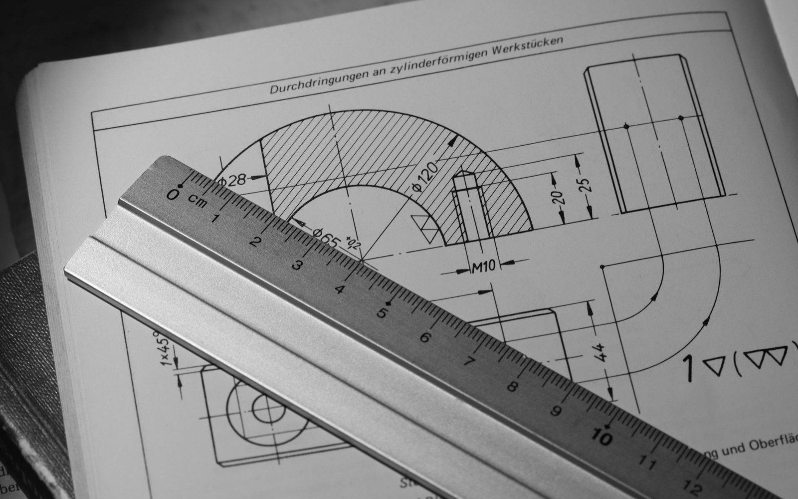
Three drawing types, one building — and the distinct question each sheet answers
Each answers a different question. Together, the plan, the section, and the elevation drawing constitute the minimum documentary set — the three views without which a builder attempting reconstruction cannot work. The 1920s survey of the Zabłudów synagogue, carried out under the Warsaw University of Technology fieldwork programme, produced sheets in all three categories, and understanding what each type records is a prerequisite for reading them correctly.
The plan: what occupies the ground
A plan drawing is a horizontal cut through the building, typically made at roughly window-sill height, and the result is read as if looking straight down. What it shows, above everything else, is wall thickness. In notched-corner log construction — the structural system used at Zabłudów, in which horizontal logs are locked at each corner by interlocking notch cuts without nails or a separate frame — wall thickness is not a decorative or insulating decision; it is the structural one. The plan records how thick those logs run, where the corners fall, how door and window openings interrupt the wall, and where internal partitions divide the space.
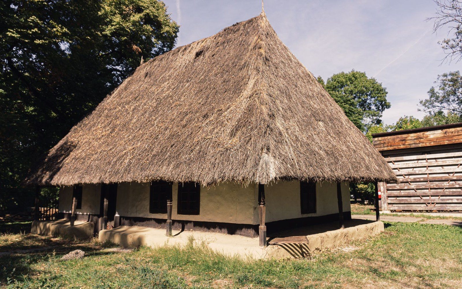
At Zabłudów, the plan also locates the bimah — the raised central platform from which the Torah is read — in relation to the surrounding prayer-hall walls. Because the bimah occupied the centre of the main space and its columns rose to the ceiling, its position in the plan is not incidental: it is the datum from which the interior's proportional system can be reconstructed. A plan without that information is architecturally incomplete. The Zabłudów sheets record it.
What a plan cannot show is height. It is silent on the rake of a roof, the depth of a ceiling coffer, the number of log courses between sill and eaves. For that, the draughtsman turns to the section.
The section: what happens through the vertical
A section drawing is a vertical cut through the building, and it answers the question the plan cannot: how tall is everything, and how is the interior volume organised? At Zabłudów, where the roof structure rose above the prayer hall in a form far more complex than a simple gable, the section drawing carries a large proportion of the building's architectural information.
The shingle roof — a covering of overlapping wooden pieces split from the block and laid in stepped horizontal courses — rose in stages above the main hall. The section shows those stages: the pitch of each slope, the height at which the ceiling plane meets the walls, and the structural members that carry the roof load down through the log walls to the ground. It also shows the relationship between the women's gallery and the main floor, a distinction invisible in any plan.
For a builder reading these drawings as working documents, the section establishes the critical dimensions that govern timber procurement. Log length, rafter span, ridge height — all are readable from a correctly drawn section in a way that no photograph, however sharp, can provide. Photographic records preserve appearance; sections preserve geometry.
The elevation: what the building presents to the outside
An elevation drawing is an orthographic view of one exterior face — drawn without perspective distortion, as if the observer were infinitely far away and the building projected flat onto the drawing surface. It is the drawing type most easily confused with a photograph, and the difference matters: a photograph renders what the eye sees, with the convergence of parallel lines and the foreshortening of receding planes. An elevation drawing renders the building's actual geometry, with every horizontal course of logs at its true measured height.
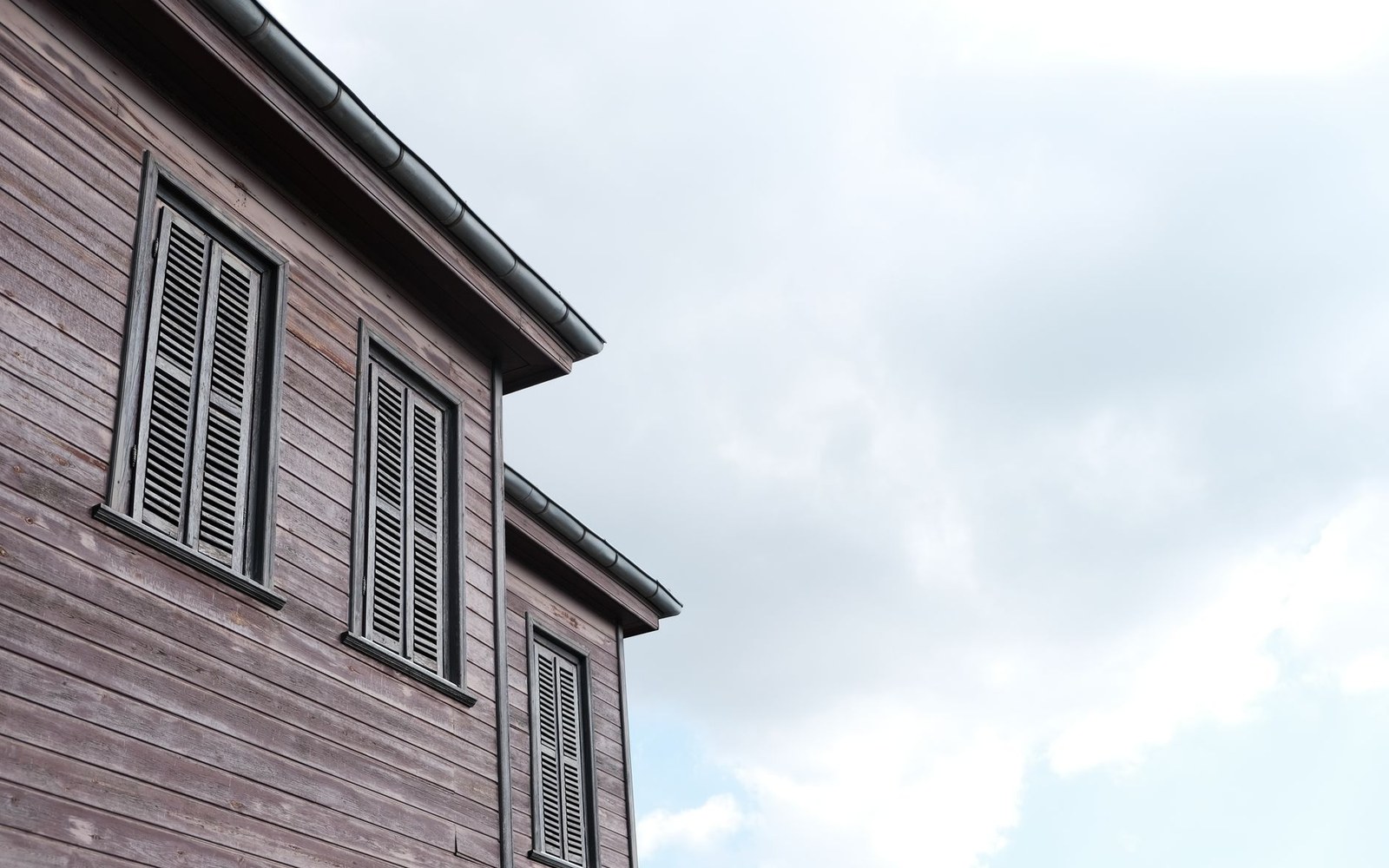
The Zabłudów elevations recorded the fenestration pattern, the proportions of each facade, and the profile of the roof as seen from outside. They also captured surface detail — carved window surrounds, the stepped weathering of the shingled slopes — that section drawings, concerned with internal geometry, leave aside.
Read together, the three drawing types function as a measured survey document in the precise technical sense: a record produced by directly measuring an existing building and translating those measurements into scaled drawings. No single sheet is sufficient. The plan locates; the section measures height; the elevation describes the face. Strip any one of the three away, and reconstruction becomes estimation.